Good progress the last few days. I received some parts from the Cozy Rirrrls a few days ago. Included in the order were the NC-3 and NC-3a hinge plate assemblies, hinge pins and other canard hardware. I had made these parts myself, however after test fitting them I was not happy with my workmanship, they probably would have worked fine, however I feel that control systems are not something to take a chance on. I decided to play it safe and order some parts from the girrrls. I am glad I did. They shipped the parts right away and the workmanship on everyting including packaging was wonderfull. Thanks Crissi, thanks Randi!.
Pictured here are the elevators mounted to the canard via four plywood jigs. The jigs secure the elevators in place while the hinge plates are floxed in place.
After the flox bonding the hinge plates cured I used the pictured template to verify the elevator travel. Full forward stick should bring the elevator to 15 degrees up. Unfortunately the elevators were only moving up to the 10 degree position.
The plans suggest that one sand away some trailing edge of the canard to fix this situation. After sanding away a little less than 1/8' from the trailing edge the elevators could be positioned to the full 15 degree forward deflection.
Here the elevator is showin in the full back position of 30 degrees down elevator. Also shown is the duct tape I used to protect the elevator while I sanded the training edge. the sanding block, and the strait edge to ensure the trailing edge was strait while I sanded away.
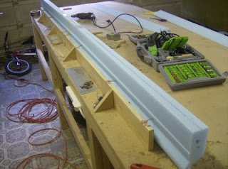
If you look closely you can see two of the elevator jigs reinstalled (with Bondo) to the mid underside of the canard to hold the elevators at 0 degrees deflection. This is used to align a curve to the canard tips (blue foam blocks pictured).
Wednesday, November 26, 2008
Monday, November 10, 2008
Chapter 13 - Nose Gear - Part 1
Time for a little diversion....
I am in need of some parts to complete the eleveator installation on the canard, so I have turned my attention toward the nose gear.
I purchased this used worm drive nose gear retract assembly and I spent yesterday evening cleaning it up and panting it. You can see the previous owner had many lightening holes drilled into the aluminum assembly side plates and the round gear as well.
Tuesday, October 28, 2008
Chapter 10 - Canard construction - Part 8
Slow but steady progress. Over the last couple of weeks I have been taking my time glassing and assembling the elevators. Lots of little parts and steps with these. I have tried to be as careful with these parts as I can.
Here is the elevator torque tube installed in the left elevator foam core with micro. The 2 aluminium triangles ensure the tube is in the correct position.
Here are the left and right elevators fully glassed and ready to begin installation to the canard. Visible is one of the stainless steel hinge pins temporarily installed. It was used to align the end plug prior to riveting. Also visible is the hole to accept the allen set screw that will later safety the hinge pin in place.
Canard and elevators ready to be mated. You can clearly see the micro fill on the trailing edge of all three airfoils. I did a little sanding on the trailing edge of the canard, hence the dust.
Sunday, October 5, 2008
Chapter 10 - Canard construction - Part 7
My brother decided to start a project of his own about a month ago. He bought a '78 Datsun 280Z. Unfortunately it has been stuck here at my home until he can get it road worthy. Not that I mind much, but his "Z project" has been a distraction, or more really a diversion away from the my "EZ project" these last few weeks. Hence no blog update in a while. However I have been making some progress and the main canard is glassed. Also thanks to his help I have some machined parts for nearly free thanks to Deano and Jeff, my brothers co-workers that machined them for me.
Here is the canard bottom after glassing. You can clearly see the copper pipe used to keep the foam straight during the glassing process. A thicker steel pipe probably would have been preferable, but this copper pipe was available.
Here I am cutting off the foam "fish tail". Without this extra foam the trailing edge would be far to delicate prior to glassing.
Just after removing this foam I realized a frustrating mistake I made. The newer Roncz plans call for a 1" wide strip of peal ply to the trailing edge just prior to glassing the bottom. However the original plans clarify this and tell you to apply the 1" peel ply only halfway onto the trailing edge. Unfortunately I did not catch the later point and was left with one full inch of peel ply to remove from between the bottom glass ply and the training edge foam. The result was quite a bit of damage to the foam core. This caused me some deal of grief, but the next day I masked off 1/2" of the trailing edge glass and repaired the foam with dry micro. The result was acceptable and I happily continued with glassing top spar cap and skin.
Here you can see the top spar cap laid up. Also visible is the yellow micro repair to the trailing edge and the higher density foam inserts to later receive the aluminum elevator hinges
A close up view of the elevator torque tube machined to receive the NC-2 insert pictured (gold colored part). The smaller hole will recieve a stainless steel hinge pin while the larger hole is mearly to accept a pop rivet that will secure the NC-2 into the torque tube. These parts were machined by my brothers co-workers, Deano and Jeff.
Finally here is the canard fully glassed and waiting for the elevator and swoopy tips. The plans call for the canard to be stored leading egde down and I have made every attempt to save the waiste foam from when the cores were made for purposes such as this.
Thursday, September 4, 2008
Chapter 10/14 - Canard construction - Part 6/Main Spar Part 1
I have been waiting now over a month for my antenna kit from RTS. In the meantime I jumped ahead and constructed the main spar jig. I used MDF and my pocket hole kit. The pocket holes made construction really fast, however some care was needed to ensure the pocket screws did not pull the jig shelf away from its proper position when they were tightened down.
I finally got impatient waiting for the antenna kit and I ordered some copper foil and toroids from Aircraft spruce. Today the parts arrived (from ACS) and I laid out the foil strips, toroids and soldered it all together. I used my multimeter to check for continuity. This weekend I hope to lay up the bottom glass.
Thursday, August 21, 2008
Chapter 10 - Canard construction - Part 5
Today I installed the bottom canard spar cap layups. A mostly harmless process, however, again it took nearly twice what the plans called for.
I nearly overfilled the spar cap trough. After finishing and sitting down to rest with a cold beverage, I started to concern myself with it, so against better advise I got up and started messing with it. Actually I am glad I did. I used the bottom contour template as a sort of squeegee and forced any excess epoxy to the ends of the spar caps, they were a little low anyhow. So in the end all is well. I will try and be a little more carefully with future spar caps to ensure they are not over filled. I can image the difficulty in sanding down the cured cap without damaging the adjacent foam.
Here is a close up of the unidirectional spar cap tape. If you look closely you can see a red thread. That thread is easily pulled out, even at the full length of the spar. After removal of the thread, the crossing glass fibers can be pulled out leaving only the heavy unidirectional glass along the length of the spar.
Here is a hight tech caveman tape dispenser I made. Also if you look close you can see the little 3" squeege I made. I epoxied the trimmed down subway bonus card into a block of wood so I could handle it better with epoxy soaked gloves. It worked out great and was free!.
The bottom contour template. This worked great as a final squeegee to ensure the spar cap was flush with the remainder of the airfoil. Because I probable used a little too much glass and epoxy there is some minor contamination to the foam. Probably trivial when compared to an overfilled spar cap.
Spar cap complete and peel plied.
Thursday, August 14, 2008
Chapter 10 - Canard construction - Part 4
Not much to say here, however there is visual progress, so I will post this update. The day before yesterday I bonded the leading edge cores to the shear web. Yesterday I layed out the 9 plywood jigs to the workbench and today I bonded the end cores in place. All cores are aloso bonded to the jigs with small dabs of 5 min epoxy. Everything lines up perfectly and I will probably not have to do any sanding due the the accuracy of the Eureka cores.
Tuesday, August 12, 2008
Chapter 10 - Canard construction - Part 3
Last Sunday I spent a few hours laying up the shear web of the canard. At first I used gray duct tape to mask everything but the shear web area, however as I started to lay up the first few plies the tape fell off. I tried to replace it but it just became a real hassle. I ended up dispensing with it altogether. If I were to do this again I would try masking tape perhaps. In the end a few drips of epoxy got on the foam, not a big deal though.
Everything else went smoothly and as the plans instructed, except, it again took about twice as long as the plans called for. Either I am slow, or Burt and Mike had assistance while doing these tasks.
The dowels in the picture are for aligning the leading edge cores, which will be bonded in place tonight after I finish some minor trimming required due to the lift tab thickness.
Here is a close up of the lift tabs. As you can see I have alodined them. A two part process that involves first cleaning them with an acidic wash and then dipping them in alodine, chemical that protects the parts from corrosions and preps them for primer.
Saturday, August 9, 2008
Chapter 10 - Canard construction - Part 2
While I have been waiting for the canard cores from Eureka I have been fabricating some of the hardware and working on the jigs. Pictured are the nut plates, lift tabs and hinges. I have drilled out the rivets in the nut plates because I have decided to use alodine on all the parts before assembly.
Today the Eureka cores arrive, however to rain on my parade a little, as I was opening the box I discoverd a nasty gash in the box. I suppose some people just can't understand "handle with care".
Here are the ailerons. One of them had one corner smashed off.
Fortunately the peice was easy enough to glue in place. Not as big a deal as I first feared.
The cores are really nice. I am glad I ordered these instead of messing around with a hot wire saw. I also was able to compare them to prints of my CAD drawings of the cannard and they are almost an exact match.
Here the inner aft cores are jigged up for the shear web.
And here the nut plates are recessed into the core shear web area. The two inner cores are also bonded together, note the nails bondoed to the jig to keep them stationary while the epoxy/micro cures.
Thursday, July 31, 2008
Chapter 10 - Canard construction - Part 1
Well here I begin with an all new part of this project, the canard. I finally get to let the fuselage rest and collect some dust while I work on something different.
I am going to build the "Special performance canard" or better known as the Roncz R1145MS.
Rutan stopped selling plans so I have figured out a way of scaling the scanned images available on the TERF-CD. With that and some other data I have found, I feel confident that I can produce accurate jigs for this part of the project. However, to ensure that the canard is built as accurate and correct as possible and to minimize tooling and time, I have placed an order with Eureca CNC for precut cores. I have heard good things about the quality of Steve's (the owner, creator, etc of Eureka) product.
Unfortunately (for me anyhow) at this time Steve is at Oshkosh and he will not be able to ship my canard cores until next week at the soonest. So, in the meantime, I have begun fabricating some of the hardware. Pictured are the two aluminum lift tabs and the nut plates I made from anchor nuts riveted to an aluminum plate.
Sunday, July 20, 2008
Chapter 9 - Complete!
Finally chapter 9 is complete. Today I finished fairing the landing break and installing the linear actuator. To be truthful I actually need to do some finish work on the top bracket and the landing break and surrounding areas still need some finishing work. I just don't want to get to crazy making everything perfect until the finishing stages of the project.
A couple of photos of the landing break:
And a video for your viewing pleasure:
A couple of photos of the landing break:
And a video for your viewing pleasure:
Saturday, July 5, 2008
Chapter 9 - Main gear - Part 3
Progress on this project has been quite slow lately. I have been very slowly working on getting the main gear axles installed. The plans do not describe this process in much detail and I had a hard time figuring out how to mount the flat axle and flat aluminum plate to a somewhat oval shaped strut.
I ended up laying a thin flox bed on the strut and clamping the axle in place with some plastic in place to keep the strut from bonding. I then sanded the flox flat.
Then I spread the strut apart with a come-a-long and wedged it with a 4x4. I then mounted it upside down on the fuselage. I was not quite clear why this was recommended (by a forum contributer) however I realized was able to ensure the axles were mounted at the same waterline (height) when the full weight of the aircraft is bearing down on the gear.
I then took the strut down and clamped it to the side of my work bench. I carefully measured for toe in and sanded the cured flox flats until the axles were in the proper position. I then layed up 6 ply of bid and, using clamps, bonded the axles to the strut.
After the axles were cured and glass trimmed, I bonded 3"x3" aluminum plates to the inside of the strut with 10 layers of bid (I used 10 to ensure the plate was relatively flat and parallel to the axle. After that cured I trimmed the aluminum plate and made fine adjustments to the strut to ensure the break parts will not bind on the strut.
You may notice the many hardware store washers on the bolts mounting the axles. The bolts are too long and I will order some shorter bolts and discard the washers.
Saturday, May 17, 2008
She stands!
Not much real progress to report here. I have almost completed the landing gear mounting steps and tomorrow I will begin preparations for mounting the axles.
Nevertheless I think this is sort of a milestone because the bird is standing on its own two feet for the first time.
First time on it's own two (soon to be three) feet (soon to be wheels)....
Nevertheless I think this is sort of a milestone because the bird is standing on its own two feet for the first time.
First time on it's own two (soon to be three) feet (soon to be wheels)....
Thursday, May 15, 2008
Chapter 9 - Main gear - Part 2
More work on the main gear today. This stage has turned out to be quite involved. But I am almost done. Unfortunately I only ordered two of the large washers that are to be floxed and glassed to the outside of the gear attach tabs. I will need to order two more and flox/glass them in place to complete this step.
Here the outer glass tabs are ready with flox fillets for the inner glass tab layups.
Here are the first of the inner glass layups. The clamps are lightly tightened down to hold the glass layers in place during cure.
The inner glass layups completed, cured and trimmed. Holes bored through all layups and the steel tube inserted.
The plans call for a foam peice to be shaped and inserted between the steel tubes and the main gear. However it was suggested that the foam piece be replaced with flox, which is what I did. After troweling on the flox I layed up two plies BID over the tubes and the outer washers (only on the left tabs because I ordered two few, the other two will be installed when I have them in from ACS).
Saturday, May 10, 2008
Engine mount
Time for a little diversion. I am awaiting a counter bore tool and some hardware from ACS to finnish up the mounting of the main gear strut. In the meantime I have been working on an engine mount I acquired. After some unexpected debating between folks on the builders forum, I settled on refurbishing the mount as follows:
First was to bead blast, followed by a primer coat and finally a few coats of white paint. At first I intended to have the mount powder coated. However it was advised from a few sources that powder coating could make detection and repair of any cracks that may form (apparently a common occurrence with these mounts) more difficult. I also removed all the little screws you can see pictured and squirted in some linseed oil to deter corrosion.
Here is the mount as I received it..
After bead blasting by my brothers coleages Jeff and Deano. Thanks guys!
Jeff and Deano discovered two "cracks" I am not sure if they really could be considered cracks or just minor weld defects. They went ahead and performed two pea sized repairs....
Then after squirting some linsead oil into the tubing (through the little screw holes), the mount was primed..
And painted...
Subscribe to:
Posts (Atom)