Monday, December 21, 2009

Chapter 14 - Center section Spar - Part 2

We had quite the cold snap here in the north west and heating the shop to acceptable temperatures had been futile until late last week. With the help of a couple of heaters I managed to get the shop warmed up enough to do some layups.

Here is the inside of the center section spar with the internal glass plies and bulkheads. In this photo the top of the spar is on the right. The bottom, on the left, has a slight dihedral. The aft face is down and the forward face is up. In the right background is pictured the 3 panels, glassed on the inside surface, that will be the forward face of the spar.

Here is another picture of the 3 forward panels ready to micro in place.

Here pictured is the spar after the forward face has been bonded in place and the spar cap troughs have been carved.

Pictured here are the 6 1/4" attachment point reenforcement pieces. Each of these locations will later be drilled to receive 1/2" bolts attaching the wings to this center spar.

And yesterday I completed laying up the center spar shear web. Next up are the spar caps.


Wednesday, December 2, 2009

Chapter 14 - Center section Spar (and misc photos)

Materials for my Center Section Spar should arrive via the magic brown van tomorrow.

While waiting for the materials (1/4" divinicell foam, aluminium, fiberglass and epoxy) I dug out the spar jig that I built many months ago. I cut the urethane foam parts (which are pictured test fitted into the jig).

I also cut the 1/8" aluminium attachment renforcement peices (the remaining reinforcement parts will be cut when I recieve the 1/4" stock tomorrow).

Finally I cut the 8 spar cap templates.

MISC. Photos...

Here is a photo of a cover I installed just forward of the instrument panel. the two triangular "flanges", just aft and on the left and right of the panel, will provide a surface for the a gasket on the canopy to seal against.

Also here is a picture of the final nose shape. My brother commented that I never posted a final photo. The top of the nose still remains to be glassed because I want better access to install brake resivoirs and other items before it is glassed in place. I also want to find a clean way of instlling the access hatch.

Sunday, November 15, 2009

Chapter 13 - Nose - Complete!

Ok, I admit that saying this chapter is complete is a little inaccurate. I still have to install the static port, pitot tube and complete the nose access hatch. However I am going to wait on closing up the nose until more work in that area is complete. Next up will be the main spar.

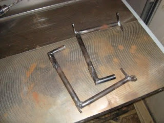
I finally have finished fabricating all of the rudder/brake pedal parts. Tomorrow I should be receiving some hardware from Aircraft Spruce to complete the installation. What follows are some photos of the left pedal test assembled:

Here is a shot of both pedals. Only the left (pictured on the right) has the brake parts installed at this stage.

Here is a shot of the pedal in the position it will normally be, with the rudder un-delployed.

Here the pedal is in the positioned where the rudder will be fully deployed, but just before brake pressure is applied.

Another shot in the un-deployed state:

Wednesday, October 14, 2009

Chapter 13/18 - Nose and Canopy - Part 6

It has been a while since I have done any work on my project and I have been getting a little upset at myself for not making more progress. So, today I got back into the shop and finished up fabrication of the the rudder/brake pedals.

I am finding gas welding a little easier now, however I wouldn't say I am good at it yet. The following pictures show the completed rudder/brake pedals. The plans call for the brake master cylinders to be mounted on the firewall and are actuated by a cable via a bell crank (also mounted on the firewall).

Most folks these days are opting to mount the master cylinders up front to make for extra room for O-320 installation.

The design of the linkages are my own, however they are inspired by examples of others I have seen on the web.


Here is the pedal in the neutral position (rudder not retracted).

And here is the position of the rudder pedal with the rudder in the fully extended position and just before any brake pressure is applied.

And finally the full rudder and brake pressure position.

Thursday, September 17, 2009

Chapter 13/18 - Nose and Canopy - Part 5

Slow progress lately. I did some more finish work on the canopy frame and I still have quite a bit more to go.
I have also done more work up front in the nose area. I fabricated nose access panel, completed the canard attachment installation including reinforcement layers of glass and installation of the nutplates.

Also after much practice I have nearly finished welding the rudder pedals. They certainly are not pretty, but I think they will work out fine. I still need to attach some sort of bracket to attach each brake master cylinders, however I will wait until I have those on hand and know exactly how they will be installed.


Sunday, August 9, 2009

Chapter 13/18 - Nose and Canopy - Part 4

Wow, over a month since my last post, and I have done so much work.

I had promised to post an update after the interior canopy glass layups were completed, but I got a little carried away and nearly finished the canopy on the inside. I also worked a little on finnishing the canopy exterior with micro fillets. Here are some photos of my progress over the last month...

Here I have completed glassing the lower half of the nose after flipping the aircraft upside down. At this stage the task of rolling the airplane over with landing gear installed is just barely manageble by myself.

Here is a photo of the interior of the canopy, nearly finnished and ready for primer. I probably have a couple more micro applicatoins and final sanding. I was a little concerned after initial glassing that the pexiglass, fiberglass joint would be so ugly, however with a little masinking tape and micro, the final result will be quite nice.


Here area few shots of the canopy exterior after the first couple of micro applications to give a nice even transition from the fiberglass skin to the pexiglass. A couple more micro applications will make the transition really nice. I also will have some work to make a nice clean transition/joint where the canopy and fuselage meet.


Monday, June 29, 2009

Chapter 13/18 - Nose and Canopy - Part 3

The following photos do not quite describe the amount of work that I have done to the Long-EZ over the last couple off weeks. I will try here to sum up what has been happening with the project.

After shaping the nose, canard cover and canopy frame, I glassed the canopy, a task that again took way longer than the plans call for, and removed it for interior glassing. Pictured here is the inside of the canopy after initial shaping of the foam. The voids along the left and right side will be filled with many fl ox and bid layers to create hard points for the hinge and canopy latch attachment. Unfortunately I did not take a photo of the canopy fully glassed before I removed it for interior shaping. I will post an update as soon as the interior is glassed.


Here is the nose and canard cover glassed. The nose has only been glassed on the top two thirds. The remainder of the nose will be glassed after I glass in the elevator fairings, remove the canard and flip the fuselage over.

Here are a couple close ups of the elevator fairings. All of the different components appear to fit together pretty roughly, however I am confident that a little micro and patience will make this all look really nice.


Tuesday, June 16, 2009

Chapter 13/18 - Nose and Canopy - Part 2

Throught the last week I have been working on the nose and canopy frame.

Just this last weekend my brother came down from Seattle and helped begin the shaping of the nose. We also began work on the canopy frame and canard cover.

Here is the floor of the nose. If you look closely you can see the 2" foam block I have used to place the forward bulkhead a little further forward. I later bonded 4 2" foam blocks to the forward face of this bulkhead. This gave me a nose shape that is about 4" longer than stock. Not enought to place a battery forward for added weight and balance options but it does help give a nice smooth nose shape.

Here is another view of the nose with the sides installed and glassed. More clearly visible is the 2" (blue) block of foam between the sl30s and the forward bulkhead.

Another view

Here is the final shape of the nose....

...before my brother had his way with it. You can also see how I have began to shape the canopy frame and canard cover all at the same time to ensure a nice smooth transition.


Here are some more views, still a little work to do but a good start.


Tuesday, May 26, 2009

Chapter 17/Section IIL - Pitch trim and Throttle Quadrant

While awaiting the arrival of the canopy I sort of got sidetracked and began to work on more of the left front console. What follows included the completion of the pitch trim handle installation as well as the installation of the throttle quadrant. 

For a year or so now I have (when bored) thumbed through my Wicks and ACS catalogs and I always really liked the looks of the RV throttle quadrants. Unfortunately there is not a reversing option available. Reversing is of course necessary because the engine is in the rear. After some thought I realized it should be a simple matter to replace the aluminium bars with some extra long ones, thus providing the reversing function. I painted them black, however I may have them anodized to match the rest of the unit in the future.

I really don't know if selection of this quadrant was a good idea, it was sort of expensive, it took quite a bit of time to get it to fit right and installation at this time is not necessary, however I like the results. The quadrant provides a throttle and mixture controls. Carb heat (if necessary) will be controlled via a push pull knob mounted on the panel near the quadrant. In order to use this set up I will make the entire left console removable so access to trim and throttle cables will be accessible.

Here is the pitch trim handle installed.


Here is the throttle quadrant install on the left front console. Pictured are the extra long control bars to allow for reversing the action of the engine controls. Also an aluminium bracket that will eventually be bolted to EZ point fasteners.


Here is the console and throttle quadrant test fitted into the cockpit. Also visible is the friction lock and the friction lock cover. I will either bond the cover or screw it to the console.


Saturday, May 23, 2009

Chapter 18 - Canopy - Part 1

Yesterday the canopy was delivered to the general store down the street. Shipping is a little cheaper sometimes for larger shipments if a comercial address can be supplied. The nice fellow who ows the general store agreed to recieve the canopy and as it happens I was driving by 5 minutes after it arrived and saw the large box sitting outside. I staped in on my roof rack and brought it home to the workshop.

After unpacking the canopy I was a little suprised to find that it was already roughly trimmed. The plans (written decades ago) indicate that the canopy should be trimmed from a rectangular base leaving about a 1/4" flange around. My canopy is just trimmed strait on the bottom and aft end.

After pondering this fact for a little bit I determinded it is trivial and actually has saved me some work. I did notice thought that the aft end of the canopy did need to be trimed to the proper length.

Here is the canopy as delivered.


Pitcured here you can see how I masked and marked the aft end of the canopy for trimming. I used a cutoff wheel in my dremel tool. That worked very good and only required a little sanding to finnish.


Here is the canopy after finishing

Sunday, May 17, 2009

Chapter 19 - Pitch trim.

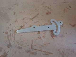
I am still awaiting canopy and other materials so, after looking through the plans for more misc. things to complete, I decided to fabricate the happy pitch trim handle yesterday.

I like the look of the aluminium and because the top portion (left in photo) of the part will be visible, I decided to clear coat the part instead of treating it with alumiprep and alodine.